




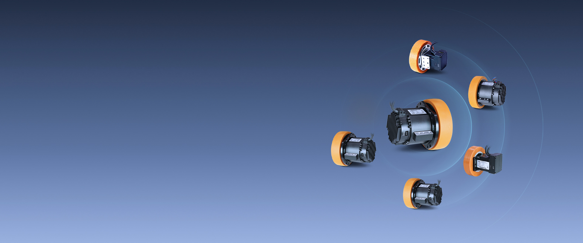
iWMC Integrated Servo Wheel Module
Drive, motor, gearbox, and wheel in a four-in-one design: effortless deployment and ultimate performance.
iWMC Integrated Servo Wheel Module
The iWMC is a four-in-one integrated drive module for wheeled mobile robots, AGVs and AMRs. It integrates a servo drive, servo motor, high-precision planetary gearbox and wear-resistant polyurethane wheel in one compact unit, reducing wiring, assembly complexity and installation space. As an integrated AGV drive system and servo wheel, it provides a reliable mobile robot drive wheel solution for intelligent mobile equipment.
| (Without STO)Integrated Servo Wheel Model (50kg~2T) | (WithSTO)Integrated Servo Wheel Model (600kg~2T) | ||||||||||||
| Model parameter | iWMC05606-00450-A150-M■DT-▶ | iWMC05606-00850-A150-M■DT-▶ | iWMC05710-01230-A130-M■DT | iWMC05710-01230-A150-M■DT | iWMC10409-02222-A165-M■DR | iWMC10411-04023-A180-M■DR | iWMC10415-05417-A180-M■DR | iWMC10420-07512-A180-M■DR | iWMC10409-02222-A165-MBDT-AS053 | iWMC10411-04023-A180-MBDT-AS105 | iWMC10415-05417-A180-MBDT-AS105 | iWMC10420-07512-A180-MBDT-AS105 | |
| Power Supply(VDC) | 24V~60V | 24V~60V | Rated 48V(24V~60V) | ||||||||||
| Logic Supply(VDC) | 24V,1A | 24V,1A | 24V,1A | ||||||||||
| Motor shaft output power (W) | 200 | 400 | 400 | 400 | 530 | 1050 | 1050 | 1050 | 530 | 1050 | 1050 | 1050 | |
| Rated speed nN (rpm) | 3000 | 3000 | 3000 | 3000 | 2000 | 2500 | 2500 | 2500 | 2000 | 2500 | 2500 | 2500 | |
| Rated Torque Tn(N.m) | 0.64 | 1.27 | 1.27 | 1.27 | 2.53 | 4 | 4 | 4.4 | 2.53 | 4 | 4 | 4 | |
| Rated current In(Arms) | 6 | 10 | 10 | 10 | 12.5A | 25A | 25A | 27.5A | 12.5 | 25 | 25 | 25 | |
| Max currentIm(Arms) | 24 | 48 | 48 | 48 | 40 | 69 | 69 | 69 | 40 | 70 | 70 | 70 | |
| Brake Holding Torque T(N.m) | 2 | 2 | 2 | 2 | 4 | 4 | 4 | 4 | 4 | 4 | 4 | 4 | |
| Whole machine | Reduction ratio | 6 | 6 | 10 | 10 | 9 | 11 | 15 | 20 | 9 | 11 | 15 | 20 |
| Rated power (W) | 190 | 379 | 379 | 379 | 500 | 950 | 950 | 980 | 500 | 950 | 950 | 980 | |
| Rated Linear Speed(m/s) | 3.9 | 3.9 | 2 | 2 | 1.9 | 2.14 | 1.57 | 1.57 | 1.9 | 2.14 | 1.57 | 1.18 | |
| Max Linear Speed(m/s) | 5.2 | 5.2 | 2.3 | 2.7 | 2.2 | 2.48 | 1.82 | 1.82 | 2.2 | 2.48 | 1.82 | 1.37 | |
| Rated Torque Tn(N.m) | 3.6 | 7.2 | 12 | 12 | 22 | 40 | 54 | 60 | 22 | 40 | 54 | 75 | |
| Max torque Tm(N.m) | 10.9 | 21.7 | 36.1 | 36.1 | 66 | 99 | 150 | 150 | 66 | 99 | 150 | 200 | |
| Max radial force Fr(N) | 1500 | 1500 | 2500 | 2500 | 3000 | 7000 | 7000 | 7000 | 3000 | 7000 | 7000 | 7000 | |
| Max axial force Fa(N) | 280 | 280 | 500 | 500 | 1000 | 1500 | 1500 | 1500 | 1000 | 1500 | 1500 | 1500 | |
| Wheel | Tire Diameter(mm) | 150 | 150 | 130 | 150 | 165 | 180 | 180 | 180 | 165 | 180 | 180 | 180 |
| Tire Width(mm) | 40 | 40 | 35 | 35 | 39.5 | 50 | 50 | 50 | 39.5 | 50 | 50 | 50 | |
| Tire Material | Polyurethane | Polyurethane (anti-static) | |||||||||||
| Tire Hardness Rating | 73A | 73A | 85A± 2 | 85A± 2 | 85A±2 | 93A±2 | 93A±2 | 93A±2 | 85A±2 | 93A±2 | 93A±2 | 93A±2 | |
| Energy Consumption Braking | External braking resistor is required (depending on the operating conditions, mainly used for rapid starting and stopping) | External brake resistance | |||||||||||
| Energy Consumption Braking Voltage Absorption Point | None | DC63V ± 2V | DC63V ± 2V | ||||||||||
| Overvoltage alarm point | DC68V ± 2V | DC68V ± 2V | |||||||||||
| Undervoltage alarm point | DC18V ± 2V | DC18V ± 2V | |||||||||||
| Cooling Methods | Natural cooling & Body-assisted cooling | ||||||||||||
| Input Specifications | iWMC05606 2 digital inputs ,iWMC05710 4 digital inputs ;Common COMI terminal , High level: 12.5-30VDC ,Low level: 0-5VDC ,Maximum frequency: 1KHz ,Input impedance: 5KΩ. | 2 channel DI , Common COMI terminal; High level :12.5V ~ 30VDC, Low level :0 ~ 5VDC; Maximum frequency :1 KHZ ,Input impedance: 5KΩ; Min turn-on voltage < 11 v, Max cut-off voltage >5V ,Max input voltage : 30V |
2 channel DI , Common COMI terminal; High level :12.5V ~ 30VDC, Low level :0 ~ 5VDC; Maximum frequency :1 KHZ ,Input impedance: 5KΩ; Min turn-on voltage < 11 v, Max cut-off voltage >5V ,Max input voltage : 30V |
||||||||||
| Input function | Freely defined as required, the functions are as follows: drive enable, drive error reset, drive mode control, speed loop proportional control, positive limit, negative limit, origin signal, command reverse, internal speed segment control, internal position segment control, emergency stop, start to find the origin, command activation, electronic gear ratio switching, gain switching | ||||||||||||
| Output Specifications | 1 digital output common COMO terminal,Maximum output current: 100mA | 1 channel digital output , open collector output, Max load current :100mA, Max control voltage : 30V | |||||||||||
| Output function | Freely defined according to needs, the functions are as follows: driver ready, driver error, motor position to, motor zero speed, motor lock brake, motor speed to, index Z signal appears, maximum limit speed in torque mode, motor lock shaft, motor limit medium, origin finding | ||||||||||||
| Encoder output | None | Isolate output , 2 channel diferential encoders, output ABZ (one encoder output is used for drive ) 2500 lines Encoder 1 can be set throuah the software index address (23400F) |
|||||||||||
| Brake | Built-in brake and control circuit | LOCK+ and LOCK- are only allow to forcibly release the brake when the drive is in the disabled state | |||||||||||
| STO | None | 2-channel STO, STO interface can be connected with the safety controller, safety switch, safety sensor, etc., to realize the safety function of the driver. Input voltage range:24VDC±15%,Input current:2.3mA(Type),Logic level standard:IEC61131-2 Type1.Input resistance:10kΩ. |
|||||||||||
| Forced Unlock Interface | 1-way forced unlock interface, only for use when there is no power input to the servo wheel. | No external forced release interface. | 1-way forced unlock interface, only for use when there is no power input to the servo wheel. | 1-way forced unlock interface, only for use when there is no power input to the servo wheel. | |||||||||
| Protect function | Overvoltage protection, undervoltage protection, motor overheat (I2T) protection, short circuit protection, drive overheat protection | ||||||||||||
| Modbus/RS485 | Max support for 115.2Kbpsand can communicate with the controller using the Modbus RTU | ||||||||||||
| CAN BUS | Max support for 1Mbp, CANopen protocol can be used to communicate with the controller | ||||||||||||
| Noise | <65dB | ||||||||||||
| Operating Temperature | 0℃~ +40°C | ||||||||||||
| Storage Temperature | Short-term storage (within 1 month): -20°C ~65°C. Long-term storage (within 1 month): -10°C ~+55°C |
||||||||||||
| Humidity (non-condensing) | 90%RH below | ||||||||||||
| Protection Level | IP54 | ||||||||||||
| Altitude | The rated working altitude is up to 1000m above sea level. For working altitudes above 1000m, a reduction of 1.5% is required for every 100 meters of rise in altitude, with a maximum working altitude of 3000 meters above sea level. | ||||||||||||
| Atmospheric Pressure | 67kpa~106kpa | ||||||||||||
| Note: ■ = A : Without brake B : With brake ▶ = L /R (Note: - L and - R represent the output schemes of servo wheel motors, with no difference in performance) |
|||||||||||||