




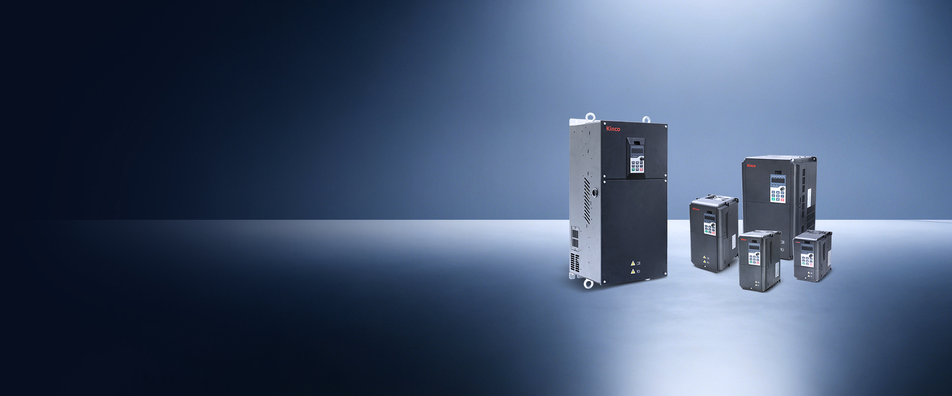
KC200 Series Inverters
General-Purpose Variable Frequency Drives
Universal Inverter
KC200 Series Inverters
Covering power ratings from 0.4 kW up to 560 kW, the KC200 series AC variable frequency drives support open-loop and closed-loop control for both synchronous and asynchronous motors.
This lineup enables reliable full-load startup at a minimum operating frequency of 0.1 Hz and features a built-in 100 kHz high-speed pulse input terminal. Modbus and CANopen communication protocols come as standard, and the products fully comply with CE certification standards.
| Item | Specification | |
| Input | Rated voltage,Rated frequency | 2S: single-phase 200V~240V 50Hz/60Hz; 4T/5T: Three-phase 380V~480V 50Hz/60Hz |
| Allowable fluctuation range of voltage | -15~10% | |
| Allowable fluctuation range of frequency | ±5% | |
| Output | Output voltage | 0~Input voltage |
| Maximum output frequency | 599Hz | |
| Overload capacity | G type machine: 150% rated current for 60s, 180% rated current for 3s | |
| Main control performance | Motor control method | V/F control,Open loop vector control (SVC), Closed loop vector control (FVC) |
| Modulation mode | Space vector PWM modulation | |
| Maximum carrier frequency | 12.0kHZ | |
| Speed control range | Open loop vector control, rated load 1:100; Closed loop vector control, rated load 1:1000 |
|
| Steady speed accuracy | Open loop vector control: ±0.5% rated synchronous speed; Closed loop vector control: ±0.02% rated synchronous speed |
|
| Starting torque | Open loop vector control: 150% rated torque at 0.5Hz; Closed loop vector control: 200% rated torque at 0Hz | |
| Torque response | Open loop vector control: < 20ms; Closed loop vector control: < 10ms |
|
| Frequency accuracy | Digital setting: maximum frequency ×±0.01%; Simulation setting: Maximum frequency ×±0.2% |
|
| Fequency resolution | Digital setting: 0.01Hz; Simulation setting: Maximum frequency ×0.05% | |
| Torque boost | Automatic torque boost; Manual torque is increased by 0.1% ~30.0% |
|
| Product basic functions |
DC braking capability | Starting frequency: 0.00Hz ~50.00Hz Braking time: 0.0s ~ 60.0s Braking current value: 0% ~ 100% rated current |
| V/F curve | Four modes: 1 user set V/F curve mode and 3 torque reduction characteristic curve mode | |
| Acceleration/ deceleration curve | Straight-line or S-curve acceleration/deceleration;Four groups of acceleration/deceleration time | |
| Multi-speed running | The product supports up to 16 speeds with the control terminal | |
| Built-in PID | The function facilitates closed-loop control of process control. | |
| Auto voltage regulation | When the mains voltage changes, the output voltage keeps constant automatically. | |
| Overvoltage/overcurrent stall control | Automatic current and voltage limit during operation to prevent frequent overvoltage trip | |
| Fast current limit | Minimize overcurrent faults and protect the normal operation of the drive | |
| Instantaneous power failure processing | The load feedback energy compensates for the voltage reduction in the transient power outage and keeps the driver running for a short time | |
| Running command | Operation panel given, control terminal given, communication control, which can be switched through a variety of ways | |
| Frequency reference | Digital setting, analog voltage setting, analog current setting, pulse setting, communication setting | |
| Auxiliary frequency setting | Realize flexible auxiliary frequency fine-tuning and frequency synthesis | |
| Input terminal | Six digital input terminals, one of which supports high-speed pulse input up to 100KHz; Two analog input terminals, one of which supports 0 ~ 10V/0 ~ 20mA input |
|
| Output terminal | Two analog output terminals, both supporting 0 ~10V/0 ~20mA output; 2 digital output terminals, one of which supports 0.1kHz ~100kHz pulse square wave signal output, which can realize the output of physical quantities such as set frequency and output frequency. 2 sets of relay output terminals |
|
| Communication | One 485 communication terminal, one CAN communication terminal | |
| Keyboard display | LED display | Single line 5-bit nixie tube, built-in keyboard and external keyboard |
| Parameter copy | The external keyboard supports uploading and downloading the function parameter information of the AC drive to achieve fast parameter setting | |
| Condition monitoring | 20 parameters such as set frequency, output frequency, output voltage and output current can be displayed | |
| Fault Alarm | Overvoltage, undervoltage, overcurrent, short circuit, phase loss, overload, overheating, etc | |
| Protect function | Phase absence protection | Input phase loss protection, output phase loss protection |
| Over-voltage protection | The main circuit stops when the DC voltage is above 800V | |
| low-voltage protection | The main circuit stops when the DC voltage is below 350V | |
| Overheat protection | Trigger protection when the AC drive bridge overheats | |
| Overload protection | Overload operation, to reach the overload time stop | |
| Over-current protection | Stop if the AC drive exceeds 2.5 times the rated current | |
| Short circuit protection | Output interphase short-circuit protection, output short-circuit protection to the ground |
|
| Environment | Installation site | In the altitude area of more than 1000 meters, due to the thin air caused by the poor heat dissipation effect of the AC drive, it needs to be derated, and 1% derated for every 100m rise |
| Temperature, humidity | -10℃ ~ +50℃, +40℃ ~ +50℃ please use derated, 5%RH ~ 95%RH (no condensation) | |
| Vibration | Less than 5.9m/s2 (0.6g) | |
| Storage temperature | -20℃~+ 60℃ | |
| Protection grade | IP20 | |
| Installation Method | Wall mounted | |