




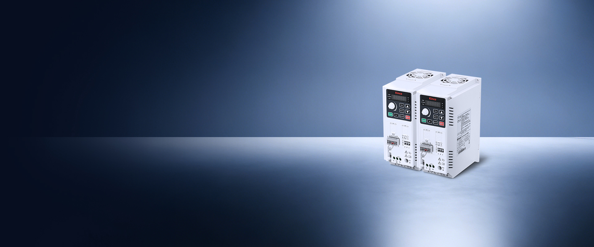
KC100 Series Inverters
Slim Book-Type Variable Frequency Drives
KC100 Series Inverters
The KC100 series AC variable frequency drives adopt a slim, compact book-style form factor and support standard DIN rail mounting.
Fitted with detachable European crimp terminal blocks, they deliver simple wiring and fast field installation. The series includes a built-in 50 kHz high-speed pulse input terminal, supports both NPN and PNP signal wiring logic, and fully complies with CE certification standards.
| Item | Specification | |
| Power input | Rated voltage,Rated frequency | 2S: single-phase 200V~240V 50Hz/60Hz; 4T/5T: Three-phase 380V~480V 50Hz/60Hz |
| Allowable fluctuation range of voltage | -15~10% | |
| Allowable fluctuation range of frequency | ±5% | |
| Output | Output voltage | 0~Input voltage |
| Maximum output frequency | 599Hz | |
| Overload capacity | 60s at 150% the rated current, 3s at 180% rated current | |
| Main control performance | Motor control mode | V/F control, Sensorless vector control (SVC), voltage frequency separation control |
| Modulation mode | Space Vector Pulse Width Modulation | |
| Carrier frequency | 0.5kHzto12.0kHz | |
| Speed range | No PG vector control: rated load 1:200 | |
| Startup torque | No PG vector control: 150% rated torque at 0.5Hz | |
| Torque response | No PG vector control: < 20ms | |
| Frequency accuracy | Digit setting: maximum frequency x (±0.01%); Analog setting: Max frequency x (±0.2%) | |
| Frequency resolution | Digital setting: 0.01Hz; Analog setting: maximum frequency x 0.1% | |
| Torque boost | Automatic boost:0.0%; manual boost: 0.1 % to 30.0 % | |
| Basic function of product | Dc braking ability | Starting frequency: 0.00Hz ~ 50.00Hz Braking time: 0.0s ~ 60.0s Braking current level: 0.0% ~ 150.0% rated current |
| V/F curve | Four Methods: multi-point V/f curve;Reduced torque characteristic curve; | |
| Acceleration/ deceleration curve | Straight-line or S-curve acceleration/deceleration;Four groups of acceleration/deceleration time | |
| multi-speed running | The product supports up to 8 speeds with the control terminal | |
| Built-in PID | The function facilitates closed-loop control of process control. | |
| Auto voltage regulation(AVR) | When the mains voltage changes, the output voltage keeps constant automatically. | |
| Overvoltage/overcurrent stall control | The function limits the current and voltage automatically during operation to prevent frequent trips caused by overvoltage or overcurrent. | |
| Fast current limit | The function helps minimize overcurrent faults. | |
| Power dip ride through | Load regenerative energy compensates for voltage reduction during instantaneous power failure, allowing the AC drive to continue operating for a short time. | |
| Running command | Running commands can be given through the operating panel, control terminal, or serial port communication, which can be switched over in various ways. | |
| Frequency reference | digital settings, analog voltage, analog current,pulse, or serial port communication. | |
| Auxiliary frequency reference | It can implement fine tuning of the auxiliary frequency and frequency synthesis. | |
| Input terminals | 4 digital input terminals, 1 of which supports high-speed pulse input up to 50KHz 1 analog input terminal, support 0 ~ 10V/0 ~ 20mA input |
|
| Output terminals | 1 relay output terminal, including normally closed and normally open sub 1 analog output terminal, support 0 ~ 10V voltage output 1 digital output terminal, 0.1kHz~50kHz pulse square wave signal output, capable of outputting physical quantities such as set frequency and output frequency 1 way 485 communication terminal |
|
| Network Port | External keyboard interface | |
| Keyboard display | LED display | Single row 5-digit digital tube, with the same built-in keyboard and external keyboard |
| Parameter copy | Quick parameter copy through the external keyboard | |
| Condition monitoring | Can display set frequency, output frequency, output voltage, output current and other more than 40 state parameters | |
| Fault Alarm | Overvoltage, undervoltage, overcurrent, short circuit, phase loss, overload, overheating, etc | |
| Environment | Installation site | In the altitude area of more than 1000 meters, due to the thin air caused by the poor heat dissipation effect of the inverter, it needs to be derated, and 1% derated for every 100m rise |
| Temperature | -10℃~+50℃Request a reduction in use | |
| Humidity | 5%RH~95%RH(non-condensation) | |
| Vibration | Less than 5.9 m/s2(0.6g) | |
| Storage temperature | -20℃~+60℃ | |
| Over voltage level | OVCⅢ | |
| Class of contamination | PD2 | |
| Protection grade | IP20 | |
| Installation methods | Wall mounted,Wall mounted, guide rail installation | |