


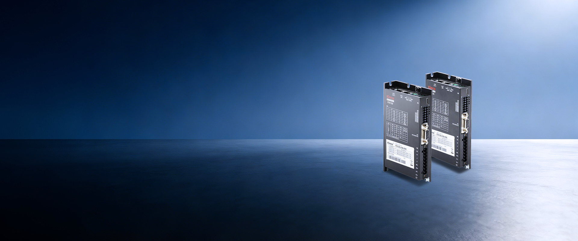
FD1X5FD1X5系列.jpg

FD1X5 Low-voltage Servo Drive

New design platform, high-performance low-voltage fifth generation servo driver

FD1X5 Low-voltage Servo Drive

The FD1X5 is our fifth-generation low-voltage servo drive, designed for a wide 24–60 VDC supply voltage with power coverage ranging from 200 W to 2000 W. It supports a comprehensive range of industrial fieldbus interfaces including CANopen, Modbus RTU and EtherCAT, and is fully compliant with CE, RoHS 2.0 and UL global safety standards. Built on an all-new auto-tuning algorithm architecture, the drive integrates adaptive notch filter and S-curve acceleration profiles to effectively dampen mechanical resonance and operational noise, delivering consistent, ultra-smooth motor rotation.

Product Model

FD125-AB-000

FD125侧面.png

Add comparison

Cancel comparison

FD125-AU-000

FD125侧面.png

Add comparison

Cancel comparison

FD125-EB-000

FD125侧面.png

Add comparison

Cancel comparison

FD125-EU-000

FD125侧面.png

Add comparison

Cancel comparison

FD135-AB-000

FD135正面.png

Add comparison

Cancel comparison

FD135-AU-000

FD135正面.png

Add comparison

Cancel comparison

FD135-EB-000

FD135正面.png

Add comparison

Cancel comparison

FD135-EU-000

FD135正面.png

Add comparison

Cancel comparison

FD145-AB-000

FD145(Y).png

Add comparison

Cancel comparison

FD145-AU-000

FD145(Y).png

Add comparison

Cancel comparison

FD145-EB-000

FD145(Y).png

Add comparison

Cancel comparison

FD145-EU-000

FD145(Y).png

Add comparison

Cancel comparison

Slide to display more

Electrical Specifications

Fold up

Expand

Power input

24VDC~60VDC

24VDC~60VDC

24VDC~60VDC

24VDC~60VDC

24VDC~60VDC

24VDC~60VDC

24VDC~60VDC

24VDC~60VDC

24VDC~60VDC

24VDC~60VDC

24VDC~60VDC

24VDC~60VDC

Logic power input

24VDC 1A(Optional)

24VDC 1A(Optional)

24VDC 1A(Optional)

24VDC 1A(Optional)

24VDC 1A(Optional)

24VDC 1A(Optional)

24VDC 1A(Optional)

24VDC 1A(Optional)

24VDC 1A(Optional)

24VDC 1A(Optional)

24VDC 1A(Optional)

24VDC 1A(Optional)

Max continuous output current(Arms)

15A

15A

15A

15A

30A

30A

30A

30A

50A

50A

50A

50A

Peak output current(Peak)

48Ap

48Ap

48Ap

48Ap

100Ap

100Ap

100Ap

100Ap

160Ap

160Ap

160Ap

160Ap

Basic Specifications

Fold up

Expand

Feedback signal

Tamagawa protocol single-turn, multi-turn encoder

Tamagawa protocol single-turn, multi-turn encoder

Tamagawa protocol single-turn, multi-turn encoder

Tamagawa protocol single-turn, multi-turn encoder

Tamagawa protocol single-turn, multi-turn encoder

Tamagawa protocol single-turn, multi-turn encoder

Tamagawa protocol single-turn, multi-turn encoder

Tamagawa protocol single-turn, multi-turn encoder

Tamagawa protocol single-turn, multi-turn encoder

Tamagawa protocol single-turn, multi-turn encoder

Tamagawa protocol single-turn, multi-turn encoder

Tamagawa protocol single-turn, multi-turn encoder

Energy consumption brake

Need external brake resistance (depending on the operation condition, mainly used in rapid start-stop occasions)

Need external brake resistance (depending on the operation condition, mainly used in rapid start-stop occasions)

Need external brake resistance (depending on the operation condition, mainly used in rapid start-stop occasions)

Need external brake resistance (depending on the operation condition, mainly used in rapid start-stop occasions)

Need external brake resistance (depending on the operation condition, mainly used in rapid start-stop occasions)

Need external brake resistance (depending on the operation condition, mainly used in rapid start-stop occasions)

Need external brake resistance (depending on the operation condition, mainly used in rapid start-stop occasions)

Need external brake resistance (depending on the operation condition, mainly used in rapid start-stop occasions)

Need external brake resistance (depending on the operation condition, mainly used in rapid start-stop occasions)

Need external brake resistance (depending on the operation condition, mainly used in rapid start-stop occasions)

Need external brake resistance (depending on the operation condition, mainly used in rapid start-stop occasions)

Need external brake resistance (depending on the operation condition, mainly used in rapid start-stop occasions)

Energy consumption brake voltage absorption point

The default is 63V±2V

The default is 63V±2V

The default is 63V±2V

The default is 63V±2V

The default is 63V±2V

The default is 63V±2V

The default is 63V±2V

The default is 63V±2V

The default is 63V±2V

The default is 63V±2V

The default is 63V±2V

The default is 63V±2V

Cooling mode

Natural cooling

Natural cooling

Natural cooling

Natural cooling

Natural cooling

Natural cooling

Natural cooling

Natural cooling

Natural cooling

Natural cooling

Natural cooling

Natural cooling

Weight(kg)

0.322

0.322

0.322

0.322

0.657

0.657

0.657

0.657

0.861

0.861

0.861

0.861

Logic loss power(mW)

1000

1000

1000

1000

1200

1200

1200

1200

1300

1300

1300

1300

Overvoltage alarm voltage

The default is 70V±2V

The default is 70V±2V

The default is 70V±2V

The default is 70V±2V

The default is 70V±2V

The default is 70V±2V

The default is 70V±2V

The default is 70V±2V

The default is 70V±2V

The default is 70V±2V

The default is 70V±2V

The default is 70V±2V

Undervoltage alarm voltage

The default is 18V±2V

The default is 18V±2V

The default is 18V±2V

The default is 18V±2V

The default is 18V±2V

The default is 18V±2V

The default is 18V±2V

The default is 18V±2V

The default is 18V±2V

The default is 18V±2V

The default is 18V±2V

The default is 18V±2V

Product function

Fold up

Expand

Protect function

Overvoltage protection, undervoltage protection, motor overheat (I2T) protection, short circuit protection, drive overheat protection

Overvoltage protection, undervoltage protection, motor overheat (I2T) protection, short circuit protection, drive overheat protection

Overvoltage protection, undervoltage protection, motor overheat (I2T) protection, short circuit protection, drive overheat protection

Overvoltage protection, undervoltage protection, motor overheat (I2T) protection, short circuit protection, drive overheat protection

Overvoltage protection, undervoltage protection, motor overheat (I2T) protection, short circuit protection, drive overheat protection

Overvoltage protection, undervoltage protection, motor overheat (I2T) protection, short circuit protection, drive overheat protection

Overvoltage protection, undervoltage protection, motor overheat (I2T) protection, short circuit protection, drive overheat protection

Overvoltage protection, undervoltage protection, motor overheat (I2T) protection, short circuit protection, drive overheat protection

Overvoltage protection, undervoltage protection, motor overheat (I2T) protection, short circuit protection, drive overheat protection

Overvoltage protection, undervoltage protection, motor overheat (I2T) protection, short circuit protection, drive overheat protection

Overvoltage protection, undervoltage protection, motor overheat (I2T) protection, short circuit protection, drive overheat protection

Overvoltage protection, undervoltage protection, motor overheat (I2T) protection, short circuit protection, drive overheat protection

Input And Output Signals

Fold up

Expand

Digital input specification

3 channels digital input, COMI terminal; High level: 12.5~30VDC; Low level: 0~5VDC;Maximum frequency: 1KHz; Input impedance: 5KΩ.

3 channels digital input, COMI terminal; High level: 12.5~30VDC; Low level: 0~5VDC;Maximum frequency: 1KHz; Input impedance: 5KΩ.

3 channels digital input, COMI terminal; High level: 12.5~30VDC; Low level: 0~5VDC;Maximum frequency: 1KHz; Input impedance: 5KΩ.

3 channels digital input, COMI terminal; High level: 12.5~30VDC; Low level: 0~5VDC;Maximum frequency: 1KHz; Input impedance: 5KΩ.

3 channels digital input, COMI terminal; High level: 12.5~30VDC; Low level: 0~5VDC;Maximum frequency: 1KHz; Input impedance: 5KΩ.

3 channels digital input, COMI terminal; High level: 12.5~30VDC; Low level: 0~5VDC;Maximum frequency: 1KHz; Input impedance: 5KΩ.

3 channels digital input, COMI terminal; High level: 12.5~30VDC; Low level: 0~5VDC;Maximum frequency: 1KHz; Input impedance: 5KΩ.

3 channels digital input, COMI terminal; High level: 12.5~30VDC; Low level: 0~5VDC;Maximum frequency: 1KHz; Input impedance: 5KΩ.

3 channels digital input, COMI terminal; High level: 12.5~30VDC; Low level: 0~5VDC;Maximum frequency: 1KHz; Input impedance: 5KΩ.

3 channels digital input, COMI terminal; High level: 12.5~30VDC; Low level: 0~5VDC;Maximum frequency: 1KHz; Input impedance: 5KΩ.

3 channels digital input, COMI terminal; High level: 12.5~30VDC; Low level: 0~5VDC;Maximum frequency: 1KHz; Input impedance: 5KΩ.

3 channels digital input, COMI terminal; High level: 12.5~30VDC; Low level: 0~5VDC;Maximum frequency: 1KHz; Input impedance: 5KΩ.

Digital input function

Freely defined as required, the functions are as follows: drive enable, drive error reset, drive mode control, speed loop proportional control, positive limit, negative limit, origin signal, command reverse, internal speed segment control, internal position segment control, emergency stop, start to find the origin, command activation, electronic gear ratio switching, gain switching

Freely defined as required, the functions are as follows: drive enable, drive error reset, drive mode control, speed loop proportional control, positive limit, negative limit, origin signal, command reverse, internal speed segment control, internal position segment control, emergency stop, start to find the origin, command activation, electronic gear ratio switching, gain switching

Freely defined as required, the functions are as follows: drive enable, drive error reset, drive mode control, speed loop proportional control, positive limit, negative limit, origin signal, command reverse, internal speed segment control, internal position segment control, emergency stop, start to find the origin, command activation, electronic gear ratio switching, gain switching

Freely defined as required, the functions are as follows: drive enable, drive error reset, drive mode control, speed loop proportional control, positive limit, negative limit, origin signal, command reverse, internal speed segment control, internal position segment control, emergency stop, start to find the origin, command activation, electronic gear ratio switching, gain switching

Freely defined as required, the functions are as follows: drive enable, drive error reset, drive mode control, speed loop proportional control, positive limit, negative limit, origin signal, command reverse, internal speed segment control, internal position segment control, emergency stop, start to find the origin, command activation, electronic gear ratio switching, gain switching

Freely defined as required, the functions are as follows: drive enable, drive error reset, drive mode control, speed loop proportional control, positive limit, negative limit, origin signal, command reverse, internal speed segment control, internal position segment control, emergency stop, start to find the origin, command activation, electronic gear ratio switching, gain switching

Freely defined as required, the functions are as follows: drive enable, drive error reset, drive mode control, speed loop proportional control, positive limit, negative limit, origin signal, command reverse, internal speed segment control, internal position segment control, emergency stop, start to find the origin, command activation, electronic gear ratio switching, gain switching

Freely defined as required, the functions are as follows: drive enable, drive error reset, drive mode control, speed loop proportional control, positive limit, negative limit, origin signal, command reverse, internal speed segment control, internal position segment control, emergency stop, start to find the origin, command activation, electronic gear ratio switching, gain switching

Freely defined as required, the functions are as follows: drive enable, drive error reset, drive mode control, speed loop proportional control, positive limit, negative limit, origin signal, command reverse, internal speed segment control, internal position segment control, emergency stop, start to find the origin, command activation, electronic gear ratio switching, gain switching

Freely defined as required, the functions are as follows: drive enable, drive error reset, drive mode control, speed loop proportional control, positive limit, negative limit, origin signal, command reverse, internal speed segment control, internal position segment control, emergency stop, start to find the origin, command activation, electronic gear ratio switching, gain switching

Freely defined as required, the functions are as follows: drive enable, drive error reset, drive mode control, speed loop proportional control, positive limit, negative limit, origin signal, command reverse, internal speed segment control, internal position segment control, emergency stop, start to find the origin, command activation, electronic gear ratio switching, gain switching

Freely defined as required, the functions are as follows: drive enable, drive error reset, drive mode control, speed loop proportional control, positive limit, negative limit, origin signal, command reverse, internal speed segment control, internal position segment control, emergency stop, start to find the origin, command activation, electronic gear ratio switching, gain switching

Pulse input specification

Pulse+direction, phase A+phase B(3.3V~24V)

Pulse+direction, phase A+phase B(3.3V~24V)

Pulse+direction, phase A+phase B(3.3V~24V)

Pulse+direction, phase A+phase B(3.3V~24V)

Pulse+direction, phase A+phase B(3.3V~24V)

Pulse+direction, phase A+phase B(3.3V~24V)

Pulse+direction, phase A+phase B(3.3V~24V)

Pulse+direction, phase A+phase B(3.3V~24V)

Pulse+direction, phase A+phase B(3.3V~24V)

Pulse+direction, phase A+phase B(3.3V~24V)

Pulse+direction, phase A+phase B(3.3V~24V)

Pulse+direction, phase A+phase B(3.3V~24V)

Digital output specification

1 digital output, OUT1 is an open collector output, up to 30V, 100mA drive capability, The brake 24V DC output, with FD125, FD135, and FD145 brake ports having output current of 0.5A, 0.8A, and 1A, respectively

1 digital output, OUT1 is an open collector output, up to 30V, 100mA drive capability, The brake 24V DC output, with FD125, FD135, and FD145 brake ports having output current of 0.5A, 0.8A, and 1A, respectively

1 digital output, OUT1 is an open collector output, up to 30V, 100mA drive capability, The brake 24V DC output, with FD125, FD135, and FD145 brake ports having output current of 0.5A, 0.8A, and 1A, respectively

1 digital output, OUT1 is an open collector output, up to 30V, 100mA drive capability, The brake 24V DC output, with FD125, FD135, and FD145 brake ports having output current of 0.5A, 0.8A, and 1A, respectively

1 digital output, OUT1 is an open collector output, up to 30V, 100mA drive capability, The brake 24V DC output, with FD125, FD135, and FD145 brake ports having output current of 0.5A, 0.8A, and 1A, respectively

1 digital output, OUT1 is an open collector output, up to 30V, 100mA drive capability, The brake 24V DC output, with FD125, FD135, and FD145 brake ports having output current of 0.5A, 0.8A, and 1A, respectively

1 digital output, OUT1 is an open collector output, up to 30V, 100mA drive capability, The brake 24V DC output, with FD125, FD135, and FD145 brake ports having output current of 0.5A, 0.8A, and 1A, respectively

1 digital output, OUT1 is an open collector output, up to 30V, 100mA drive capability, The brake 24V DC output, with FD125, FD135, and FD145 brake ports having output current of 0.5A, 0.8A, and 1A, respectively

1 digital output, OUT1 is an open collector output, up to 30V, 100mA drive capability, The brake 24V DC output, with FD125, FD135, and FD145 brake ports having output current of 0.5A, 0.8A, and 1A, respectively

1 digital output, OUT1 is an open collector output, up to 30V, 100mA drive capability, The brake 24V DC output, with FD125, FD135, and FD145 brake ports having output current of 0.5A, 0.8A, and 1A, respectively

1 digital output, OUT1 is an open collector output, up to 30V, 100mA drive capability, The brake 24V DC output, with FD125, FD135, and FD145 brake ports having output current of 0.5A, 0.8A, and 1A, respectively

1 digital output, OUT1 is an open collector output, up to 30V, 100mA drive capability, The brake 24V DC output, with FD125, FD135, and FD145 brake ports having output current of 0.5A, 0.8A, and 1A, respectively

Digital output function

following functions can be freely defined as needed, with the following functions: drive ready, drive error, motor position reached, motor zero speed, motor holding brake, motor speed reached, index Z signal present, maximum limit speed in torque mode, motor locked axis, motor in limit, home position found.

following functions can be freely defined as needed, with the following functions: drive ready, drive error, motor position reached, motor zero speed, motor holding brake, motor speed reached, index Z signal present, maximum limit speed in torque mode, motor locked axis, motor in limit, home position found.

following functions can be freely defined as needed, with the following functions: drive ready, drive error, motor position reached, motor zero speed, motor holding brake, motor speed reached, index Z signal present, maximum limit speed in torque mode, motor locked axis, motor in limit, home position found.

following functions can be freely defined as needed, with the following functions: drive ready, drive error, motor position reached, motor zero speed, motor holding brake, motor speed reached, index Z signal present, maximum limit speed in torque mode, motor locked axis, motor in limit, home position found.

following functions can be freely defined as needed, with the following functions: drive ready, drive error, motor position reached, motor zero speed, motor holding brake, motor speed reached, index Z signal present, maximum limit speed in torque mode, motor locked axis, motor in limit, home position found.

following functions can be freely defined as needed, with the following functions: drive ready, drive error, motor position reached, motor zero speed, motor holding brake, motor speed reached, index Z signal present, maximum limit speed in torque mode, motor locked axis, motor in limit, home position found.

following functions can be freely defined as needed, with the following functions: drive ready, drive error, motor position reached, motor zero speed, motor holding brake, motor speed reached, index Z signal present, maximum limit speed in torque mode, motor locked axis, motor in limit, home position found.

following functions can be freely defined as needed, with the following functions: drive ready, drive error, motor position reached, motor zero speed, motor holding brake, motor speed reached, index Z signal present, maximum limit speed in torque mode, motor locked axis, motor in limit, home position found.

following functions can be freely defined as needed, with the following functions: drive ready, drive error, motor position reached, motor zero speed, motor holding brake, motor speed reached, index Z signal present, maximum limit speed in torque mode, motor locked axis, motor in limit, home position found.

following functions can be freely defined as needed, with the following functions: drive ready, drive error, motor position reached, motor zero speed, motor holding brake, motor speed reached, index Z signal present, maximum limit speed in torque mode, motor locked axis, motor in limit, home position found.

following functions can be freely defined as needed, with the following functions: drive ready, drive error, motor position reached, motor zero speed, motor holding brake, motor speed reached, index Z signal present, maximum limit speed in torque mode, motor locked axis, motor in limit, home position found.

following functions can be freely defined as needed, with the following functions: drive ready, drive error, motor position reached, motor zero speed, motor holding brake, motor speed reached, index Z signal present, maximum limit speed in torque mode, motor locked axis, motor in limit, home position found.

Communication function

Fold up

Expand

USB

Debug special, can use Kinco PC software connection

Debug special, can use Kinco PC software connection

Debug special, can use Kinco PC software connection

Debug special, can use Kinco PC software connection

Debug special, can use Kinco PC software connection

Debug special, can use Kinco PC software connection

Debug special, can use Kinco PC software connection

Debug special, can use Kinco PC software connection

Debug special, can use Kinco PC software connection

Debug special, can use Kinco PC software connection

Debug special, can use Kinco PC software connection

Debug special, can use Kinco PC software connection

Modbus/RS485

Supports

Supports

Not supported

Not supported

Supports

Supports

Not supported

Not supported

Supports

Supports

Not supported

Not supported

Modbus/RS485 description

It supports a max 115200bps and can communicate with the controller using Modbus RTU

It supports a max 115200bps and can communicate with the controller using Modbus RTU

/

/

It supports a max 115200bps and can communicate with the controller using Modbus RTU

It supports a max 115200bps and can communicate with the controller using Modbus RTU

/

/

It supports a max 115200bps and can communicate with the controller using Modbus RTU

It supports a max 115200bps and can communicate with the controller using Modbus RTU

/

/

CANopen

Supports

Supports

Not supported

Not supported

Supports

Supports

Not supported

Not supported

Supports

Supports

Not supported

Not supported

CANopen description

It supports a maxof 1 Mbps and can communicate with the controller using the CANopen

It supports a maxof 1 Mbps and can communicate with the controller using the CANopen

/

/

It supports a maxof 1 Mbps and can communicate with the controller using the CANopen

It supports a maxof 1 Mbps and can communicate with the controller using the CANopen

/

/

It supports a maxof 1 Mbps and can communicate with the controller using the CANopen

It supports a maxof 1 Mbps and can communicate with the controller using the CANopen

/

/

EtherCAT

Not supported

Not supported

Supports

Supports

Not supported

Not supported

Supports

Supports

Not supported

Not supported

Supports

Supports

EtherCAT description

/

/

Support CoE(CiA402 protocol)and CSP/CSV/PP/PV/PT/HM mode,communication speed 100Mbps

Support CoE(CiA402 protocol)and CSP/CSV/PP/PV/PT/HM mode,communication speed 100Mbps

/

/

Support CoE(CiA402 protocol)and CSP/CSV/PP/PV/PT/HM mode,communication speed 100Mbps

Support CoE(CiA402 protocol)and CSP/CSV/PP/PV/PT/HM mode,communication speed 100Mbps

/

/

Support CoE(CiA402 protocol)and CSP/CSV/PP/PV/PT/HM mode,communication speed 100Mbps

Support CoE(CiA402 protocol)and CSP/CSV/PP/PV/PT/HM mode,communication speed 100Mbps

Environment Of Use

Fold up

Expand

Working Temperature

-20℃ ~ +40℃(no freezing),When the operating temperature exceeds 40°C, the driver needs to be derated,Please refer to the derating curve when the drive operates at 50℃.

-20℃ ~ +40℃(no freezing),When the operating temperature exceeds 40°C, the driver needs to be derated,Please refer to the derating curve when the drive operates at 50℃.

-20℃ ~ +40℃(no freezing),When the operating temperature exceeds 40°C, the driver needs to be derated,Please refer to the derating curve when the drive operates at 50℃.

-20℃ ~ +40℃(no freezing),When the operating temperature exceeds 40°C, the driver needs to be derated,Please refer to the derating curve when the drive operates at 50℃.

-20℃ ~ +40℃(no freezing),When the operating temperature exceeds 40°C, the driver needs to be derated,Please refer to the derating curve when the drive operates at 50℃.

-20℃ ~ +40℃(no freezing),When the operating temperature exceeds 40°C, the driver needs to be derated,Please refer to the derating curve when the drive operates at 50℃.

-20℃ ~ +40℃(no freezing),When the operating temperature exceeds 40°C, the driver needs to be derated,Please refer to the derating curve when the drive operates at 50℃.

-20℃ ~ +40℃(no freezing),When the operating temperature exceeds 40°C, the driver needs to be derated,Please refer to the derating curve when the drive operates at 50℃.

-20℃ ~ +40℃(no freezing),When the operating temperature exceeds 40°C, the driver needs to be derated,Please refer to the derating curve when the drive operates at 50℃.

-20℃ ~ +40℃(no freezing),When the operating temperature exceeds 40°C, the driver needs to be derated,Please refer to the derating curve when the drive operates at 50℃.

-20℃ ~ +40℃(no freezing),When the operating temperature exceeds 40°C, the driver needs to be derated,Please refer to the derating curve when the drive operates at 50℃.

-20℃ ~ +40℃(no freezing),When the operating temperature exceeds 40°C, the driver needs to be derated,Please refer to the derating curve when the drive operates at 50℃.

Storage temperature

-40℃ ~ +70℃(no freezing)

-40℃ ~ +70℃(no freezing)

-40℃ ~ +70℃(no freezing)

-40℃ ~ +70℃(no freezing)

-40℃ ~ +70℃(no freezing)

-40℃ ~ +70℃(no freezing)

-40℃ ~ +70℃(no freezing)

-40℃ ~ +70℃(no freezing)

-40℃ ~ +70℃(no freezing)

-40℃ ~ +70℃(no freezing)

-40℃ ~ +70℃(no freezing)

-40℃ ~ +70℃(no freezing)

Working Humidity 

Less than 90%RH

Less than 90%RH

Less than 90%RH

Less than 90%RH

Less than 90%RH

Less than 90%RH

Less than 90%RH

Less than 90%RH

Less than 90%RH

Less than 90%RH

Less than 90%RH

Less than 90%RH

Protection class

IP20 (Power supply terminal X5 only meets IP00 protection level)

IP20 (Power supply terminal X5 only meets IP00 protection level)

IP20 (Power supply terminal X5 only meets IP00 protection level)

IP20 (Power supply terminal X5 only meets IP00 protection level)

IP20 (Power supply terminal X5 only meets IP00 protection level)

IP20 (Power supply terminal X5 only meets IP00 protection level)

IP20 (Power supply terminal X5 only meets IP00 protection level)

IP20 (Power supply terminal X5 only meets IP00 protection level)

IP20 (Power supply terminal X5 only meets IP00 protection level)

IP20 (Power supply terminal X5 only meets IP00 protection level)

IP20 (Power supply terminal X5 only meets IP00 protection level)

IP20 (Power supply terminal X5 only meets IP00 protection level)

Altitude

The rated working altitude is less than 1000 meters above sea level. When the working altitude is higher than 1000 meters, it is necessary to reduce the rated value by 1.5% for every 100 meters of elevation. The maximum working altitude is 2000 meters above sea level.

The rated working altitude is less than 1000 meters above sea level. When the working altitude is higher than 1000 meters, it is necessary to reduce the rated value by 1.5% for every 100 meters of elevation. The maximum working altitude is 2000 meters above sea level.

The rated working altitude is less than 1000 meters above sea level. When the working altitude is higher than 1000 meters, it is necessary to reduce the rated value by 1.5% for every 100 meters of elevation. The maximum working altitude is 2000 meters above sea level.

The rated working altitude is less than 1000 meters above sea level. When the working altitude is higher than 1000 meters, it is necessary to reduce the rated value by 1.5% for every 100 meters of elevation. The maximum working altitude is 2000 meters above sea level.

The rated working altitude is less than 1000 meters above sea level. When the working altitude is higher than 1000 meters, it is necessary to reduce the rated value by 1.5% for every 100 meters of elevation. The maximum working altitude is 2000 meters above sea level.

The rated working altitude is less than 1000 meters above sea level. When the working altitude is higher than 1000 meters, it is necessary to reduce the rated value by 1.5% for every 100 meters of elevation. The maximum working altitude is 2000 meters above sea level.

The rated working altitude is less than 1000 meters above sea level. When the working altitude is higher than 1000 meters, it is necessary to reduce the rated value by 1.5% for every 100 meters of elevation. The maximum working altitude is 2000 meters above sea level.

The rated working altitude is less than 1000 meters above sea level. When the working altitude is higher than 1000 meters, it is necessary to reduce the rated value by 1.5% for every 100 meters of elevation. The maximum working altitude is 2000 meters above sea level.

The rated working altitude is less than 1000 meters above sea level. When the working altitude is higher than 1000 meters, it is necessary to reduce the rated value by 1.5% for every 100 meters of elevation. The maximum working altitude is 2000 meters above sea level.

The rated working altitude is less than 1000 meters above sea level. When the working altitude is higher than 1000 meters, it is necessary to reduce the rated value by 1.5% for every 100 meters of elevation. The maximum working altitude is 2000 meters above sea level.

The rated working altitude is less than 1000 meters above sea level. When the working altitude is higher than 1000 meters, it is necessary to reduce the rated value by 1.5% for every 100 meters of elevation. The maximum working altitude is 2000 meters above sea level.

The rated working altitude is less than 1000 meters above sea level. When the working altitude is higher than 1000 meters, it is necessary to reduce the rated value by 1.5% for every 100 meters of elevation. The maximum working altitude is 2000 meters above sea level.

Atmospheric pressure

86kpa~106kpa

86kpa~106kpa

86kpa~106kpa

86kpa~106kpa

86kpa~106kpa

86kpa~106kpa

86kpa~106kpa

86kpa~106kpa

86kpa~106kpa

86kpa~106kpa

86kpa~106kpa

86kpa~106kpa

Installation site

Dust-free, dry, lockable (e.g. electrical cabinet)

Dust-free, dry, lockable (e.g. electrical cabinet)

Dust-free, dry, lockable (e.g. electrical cabinet)

Dust-free, dry, lockable (e.g. electrical cabinet)

Dust-free, dry, lockable (e.g. electrical cabinet)

Dust-free, dry, lockable (e.g. electrical cabinet)

Dust-free, dry, lockable (e.g. electrical cabinet)

Dust-free, dry, lockable (e.g. electrical cabinet)

Dust-free, dry, lockable (e.g. electrical cabinet)

Dust-free, dry, lockable (e.g. electrical cabinet)

Dust-free, dry, lockable (e.g. electrical cabinet)

Dust-free, dry, lockable (e.g. electrical cabinet)

Installation method

Install vertically or horizontally

Install vertically or horizontally

Install vertically or horizontally

Install vertically or horizontally

Install vertically or horizontally

Install vertically or horizontally

Install vertically or horizontally

Install vertically or horizontally

Install vertically or horizontally

Install vertically or horizontally

Install vertically or horizontally

Install vertically or horizontally

Product certification

Fold up

Expand

CE

Yes

Yes

Yes

Yes

Yes

Yes

Yes

Yes

Yes

Yes

Yes

Yes

UL

No

Yes

No

Yes

No

Yes

No

Yes

No

Yes

No

Yes

FD1X5-NAME.png